February Update
February 17, 2024
The last couple of weeks has seen the front fascia painted and some initial track pinned into place. temporarily.
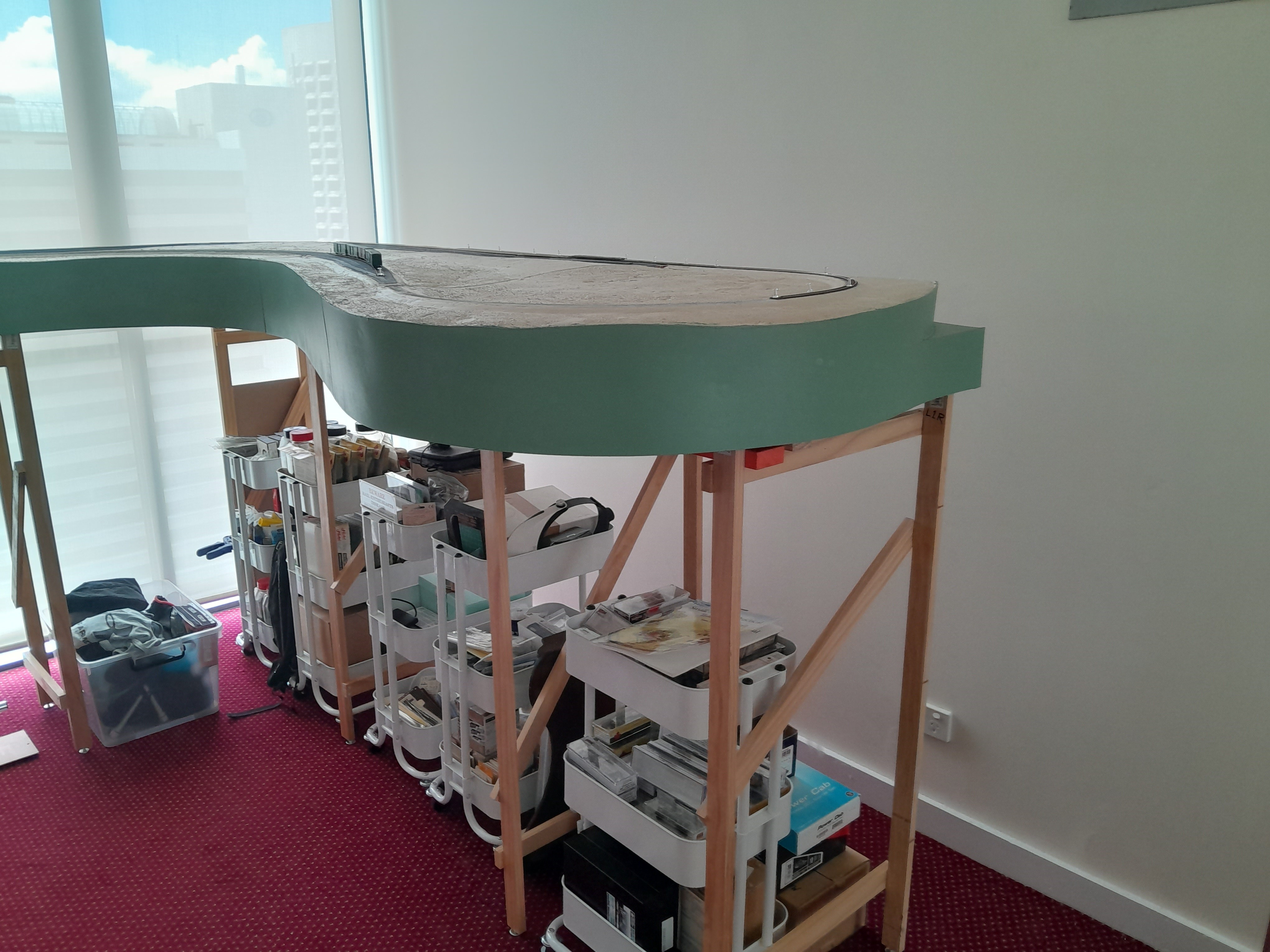
The main change on the layout over the last 2 weeks has been painting the fascia in a light green which really finishes it off nicely, even though the foam surface is only painted in a pale earth tone at this stage. Sections 1, 2 and 3 are connected together and have been moved away from the wall for staging track access. Sections 4 and 5 had their fascia painted also but they have been disconnected from the rest of the layout for now.
The colour is close to a PGE / BCR light green (Taubmans Mesa Verde for any Australians reading). Three coats applied with a roller provides a nice even finish. A fourth coat will probably be applied once all the messy scenery work has been completed (a long way off yet).


Also completed last week was some additional roadbed installation for the staging tracks. At this stage, three relatively long staging sidings are planned so roadbed was added to accommodate this. I have also started pinning down some track temporarily to get a feel for how things will look and where to make the join between Atlas Code 55 (for the visible sections) and the Peco Code 55 and points which will be used in staging.

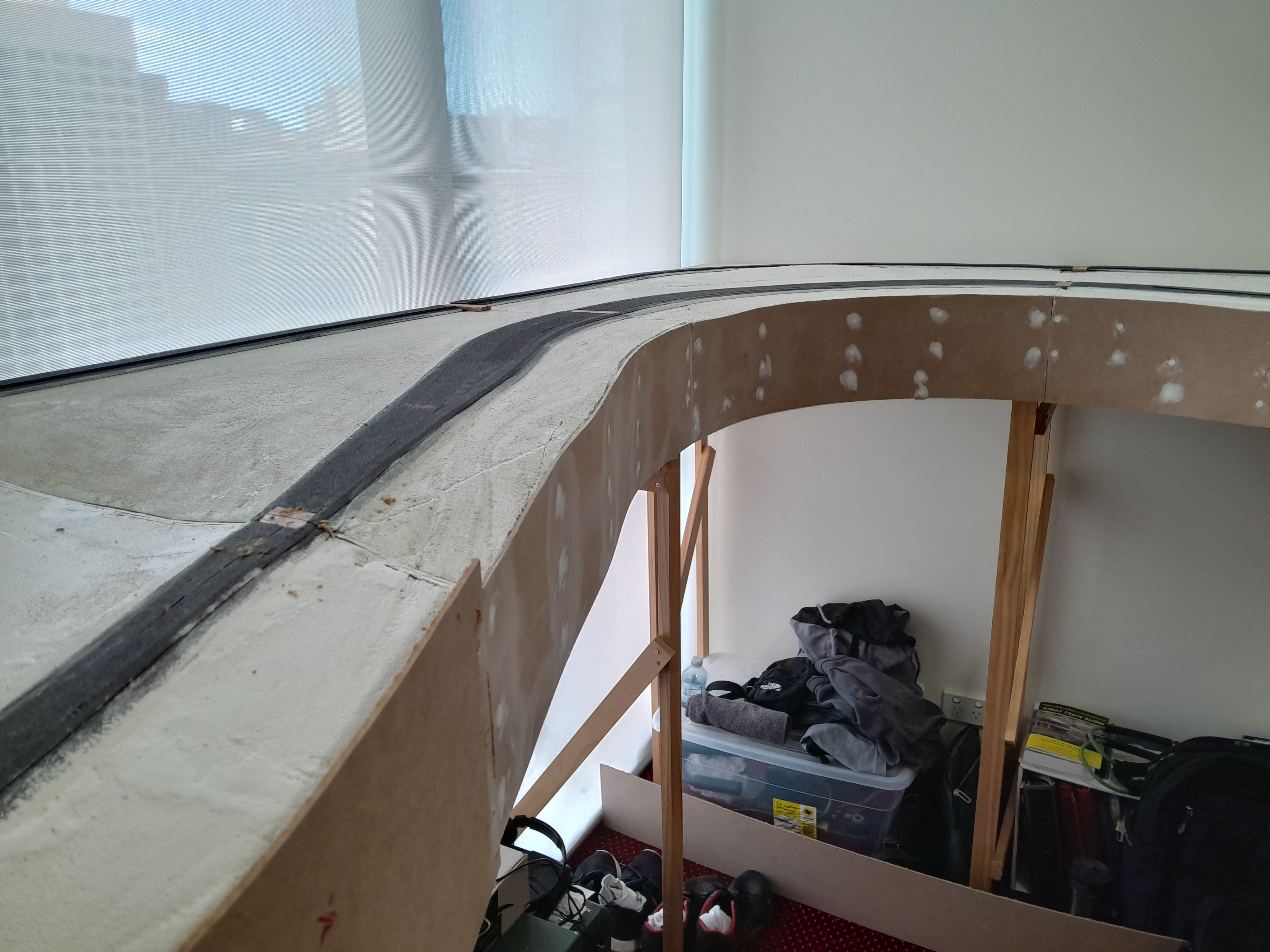
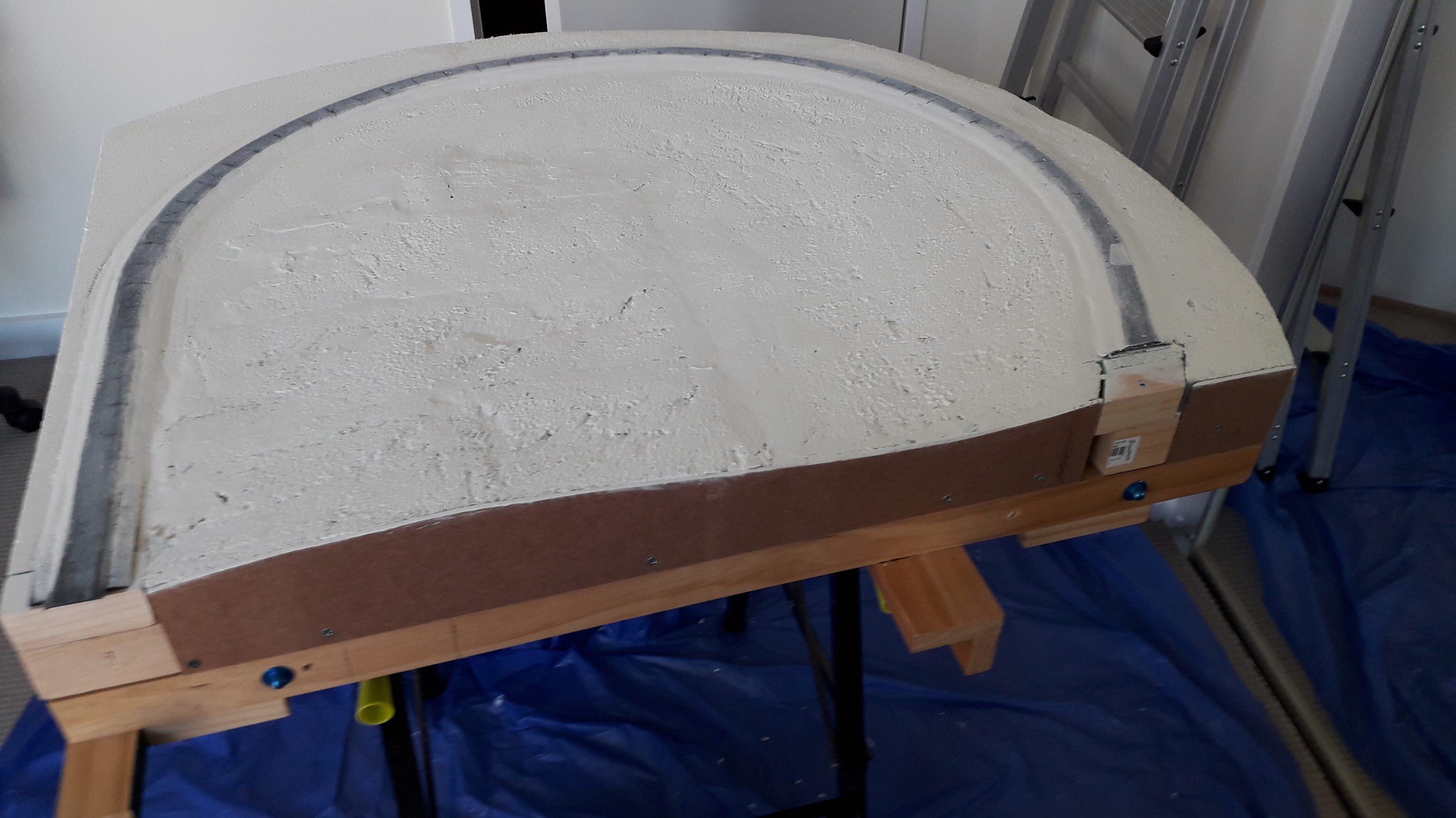
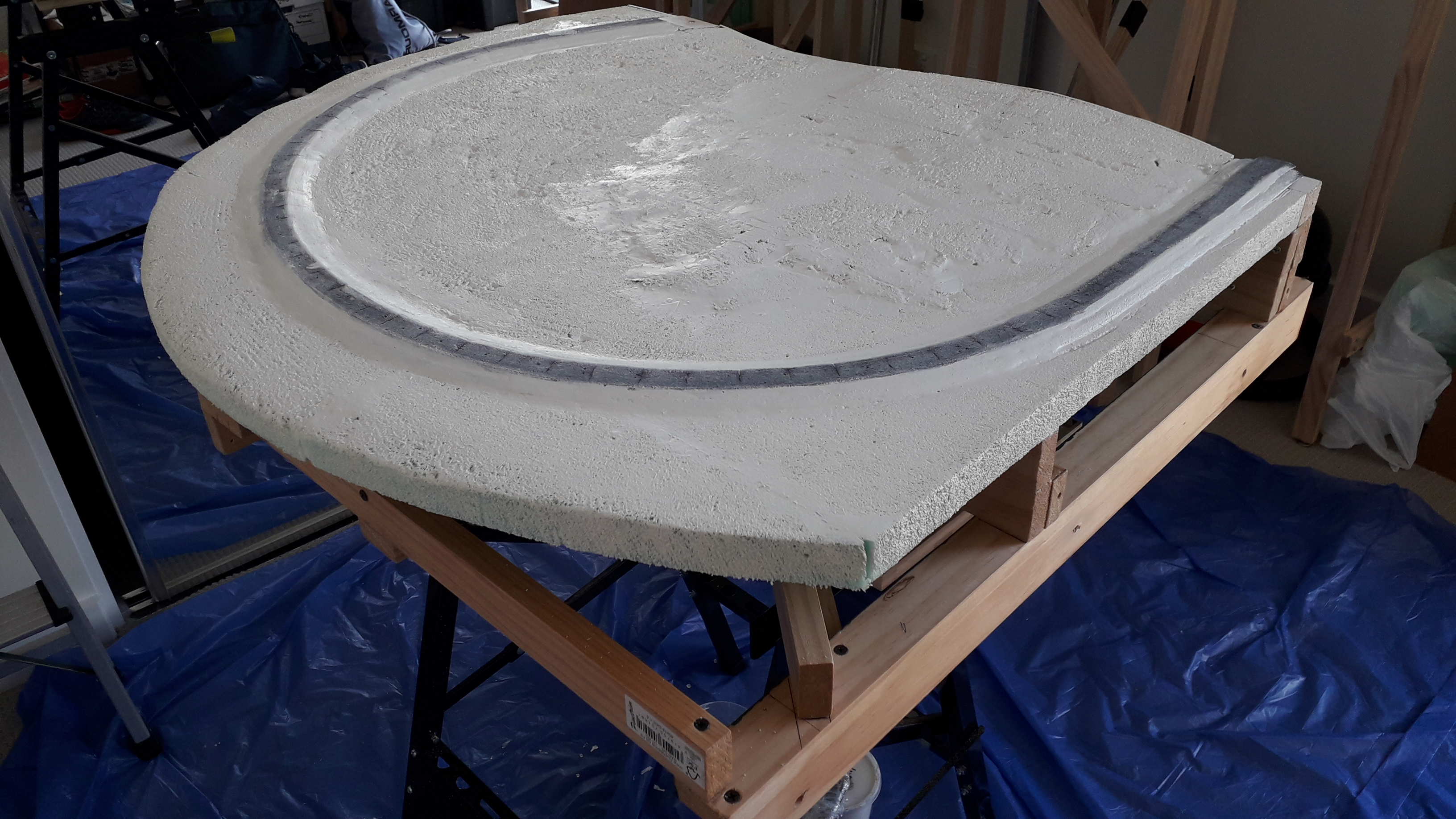
I continue to be surprised at how large the layout looks given its height (53.5 inches rail height), but this final helicopter view from an elevated position shows that it is in fact a very small layout.
The turnback curve averages a 14.5 inch radius and the maximum benchwork width of the end “blob” section is 35 inches. I could have made it narrower but wanted to allow room for some foreground scenery (and to protect against any derailments ending up on the floor). The visible length of the layout in this shot is about 5 feet and 6 inches.

Favourite Books #2 – Compact Layout Design
February 11, 2024

My second book review is one of the many Iain Rice books I have in my collection. Iain Rice is sadly no longer with us, but his books are invariably the ones I thumb through regularly. Compact Layout Design focuses on what I would call “spare room sized” layouts as opposed to the shelf and small/cameo layouts that a number of his other works focus on.
Beatton River is heavily influenced by this book, especially in the benchwork design (lightweight and portable) and the overall design philosophy which is very focused and minimalist.
As with most Iain Rice books there are several example layout case studies with his signature watercolour trackplan sketches that I just love. All the case studies in this book are HO or N scale layouts that would fit into a spare bedroom or slightly larger size space.
There were a couple of paragraphs that really jumped out at me and heavily influenced Beatton River.
“The secret of a successful layout is to create a telling rendition of your subject while modelling the minimum you can get away with, rather than trying to model every possible detail or cram in every possible feature.”
“I think it is generally accepted that so far as layout standards go, “less is more”. The less there is to model, the higher the standard you can aim to achieve.”
I am currently re-reading all the other Iain Rice books in my collection so these will definitely be reviewed here at some point soon.
Preparation for Tracklaying
February 2, 2024

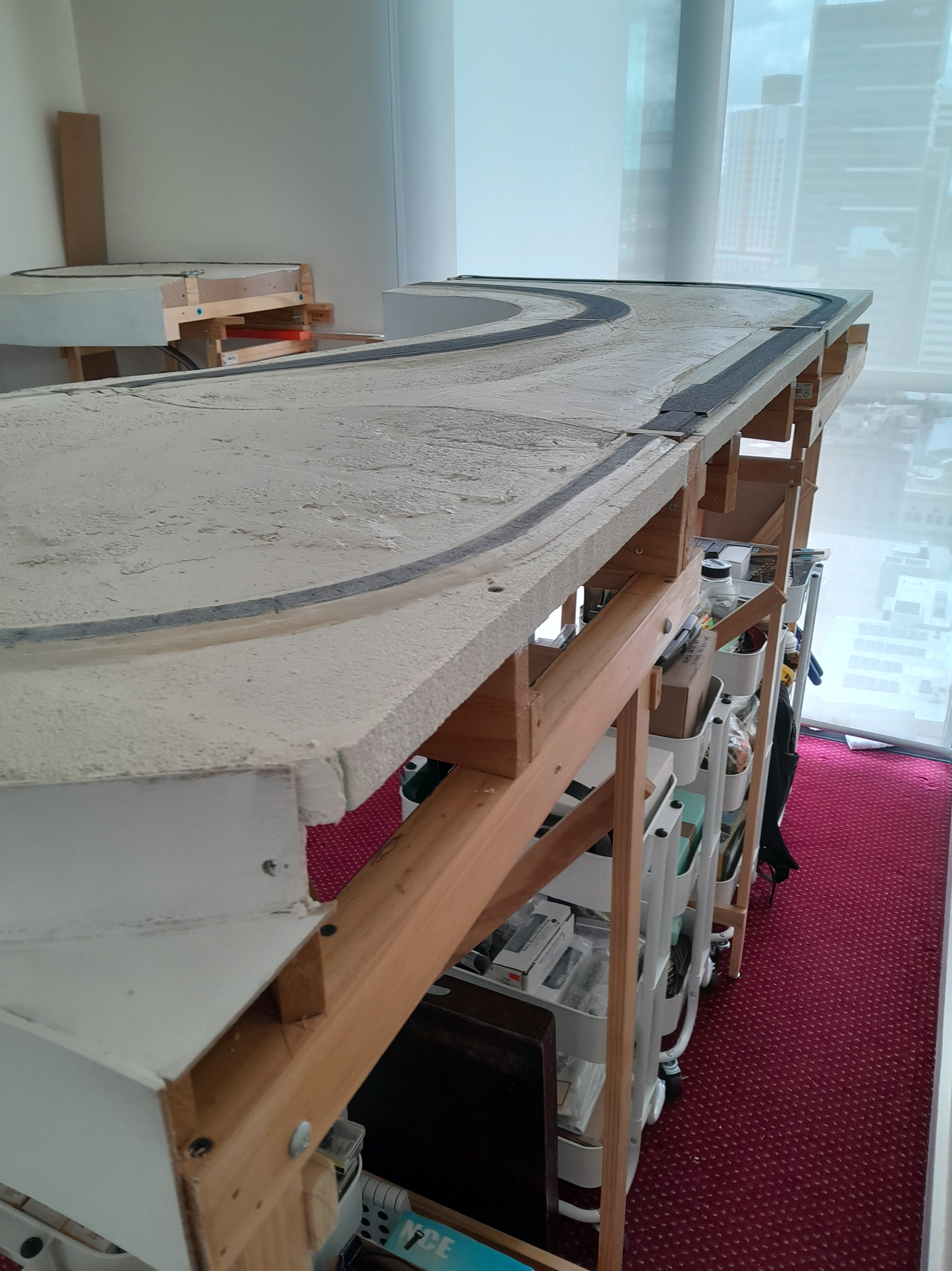
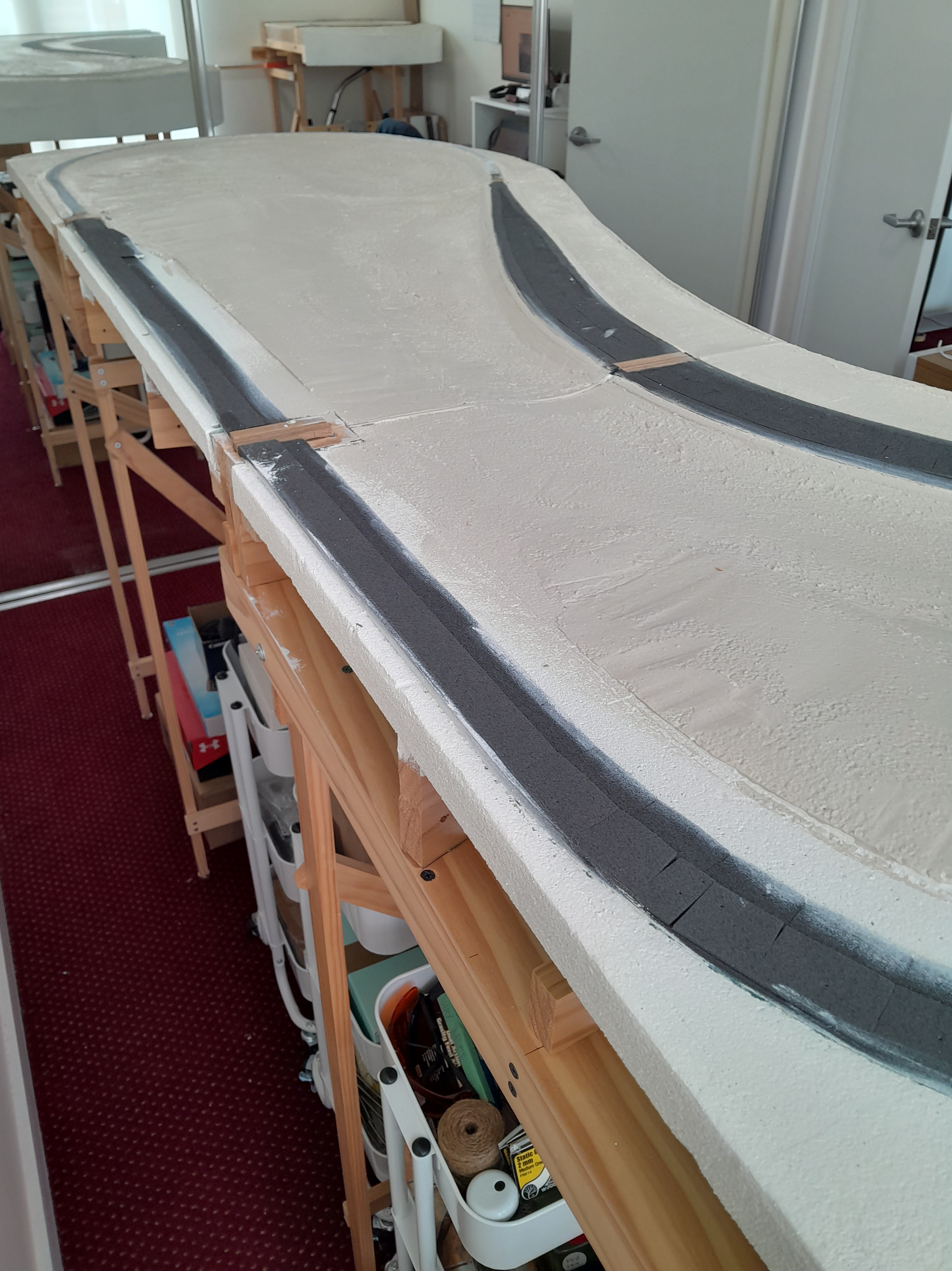
Over the last few weeks, the front fascia has been given some coats of primer and further sanding and smoothing has taken place where the screw holes were filled in. Additionally, the foam surface of the layout has been given a coat of earth coloured paint. This is to cover up the initial white paint that was used to seal the foam last year. I went with a very light beige / pebble colour that is in keeping with the colour of the soil in Northern BC. The painted foam will form the scenery base texture over which various layers or ground cover and vegetation will be added.
The final colour for the front fascia will be a light green similar to PGE/BCR light green. On past layouts I have always used a dark green for the fascia but given that the layout will be dominated by very dark green trees, I thought a light green fascia would work better.

In preparation for tracklaying, I have disconnected sections 4 and 5 and moved Sections 1, 2 and 3 away from the wall on all sides so that I have access to begin track and wiring in both the staging yard area and the visible portions. Because of the foam scenery base, the sections are very light, and they were just gently slid across the carpet as one assembly which was very handy.
I recently received a northern hemisphere shipment of Atlas track and turnouts for the visible section. Peco track and turnouts (which are much easier to get in Australia than Atlas) will be used in the hidden staging area.
Having access around the back of the layout provides a nice new viewpoint and the continuous curving design looks just as pleasing viewed from the back as it does from the front.

So, things are actually progressing on schedule. 2023 was the year to complete all basic benchwork and scenery contours. 2024 is the year of tracklaying and wiring. The goal is to have all the track down and wired and the first DCC locomotive test run before the end of the year. While I only usually work on the layout a few hours a week, this seems a reasonable goal given the simple track plan.
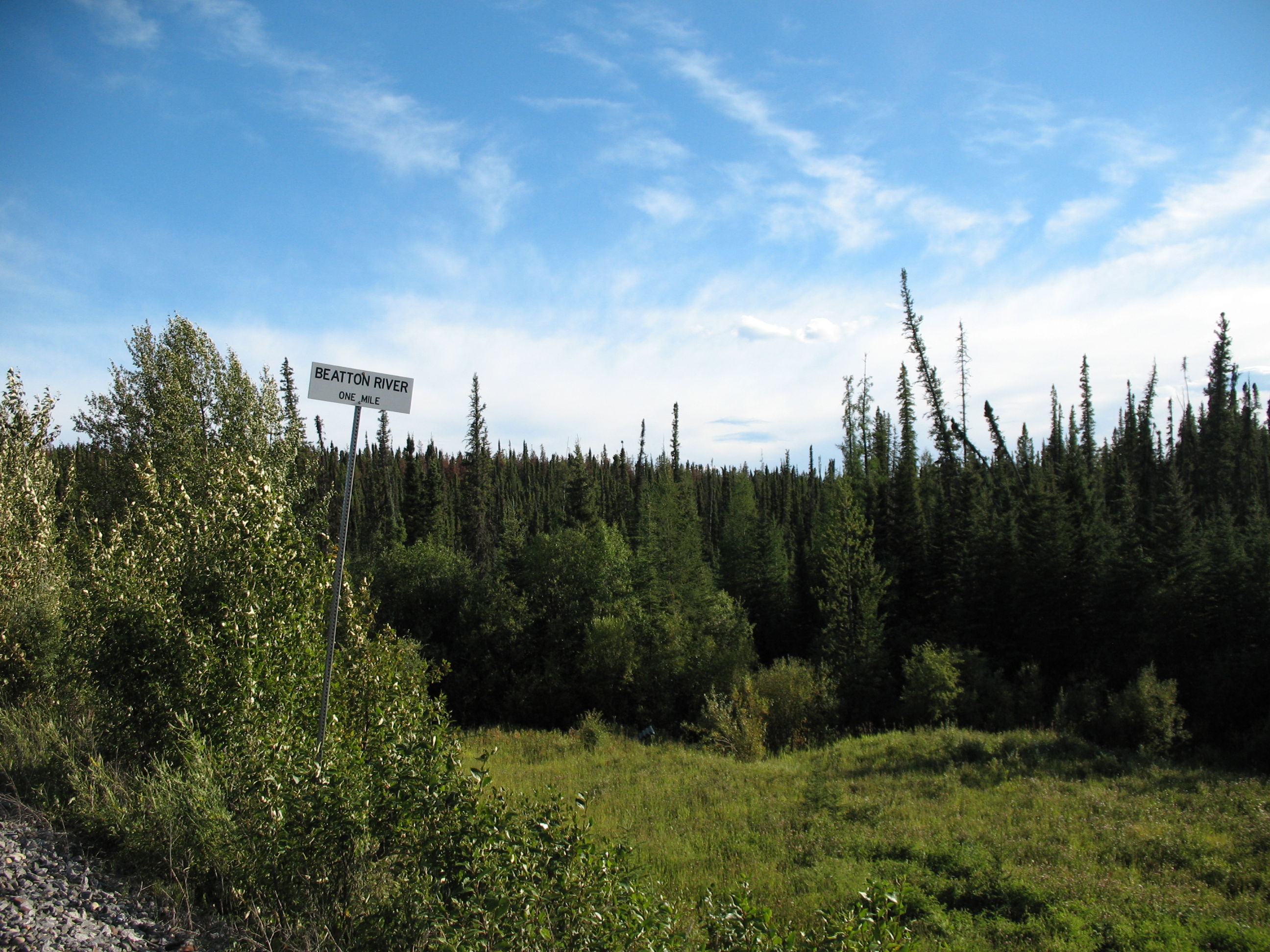
PS. The Beatton sign was a gift from a good railfan friend of mine over a decade ago. It was discovered languishing in a dumpster in Fort St John. It is a relic from the 1980s before the siding was renamed Beatton River. This 2013 photo shows the replacement sign.

Favourite Books #1- Building a Model Railroad Step by Step
January 25, 2024

Recently, my collection of books was finally liberated from plastic tubs in a closet to a proper bookshelf. With this I have started re-reading what is a fairly substantial collection acquired over the years since 2007 when I got back into the hobby.
I’ve also made something of a New Years resolution to be more selective with the digital content (blogs, forums and YouTube channels) I consume and spend more time re-reading my physical collection of books and magazines.
The first book I pulled off the shelf is an absolute Kalmbach classic. Building a Model Railroad Step by Step by David Popp is exactly what the title says. If you were new to N Scale, you could likely forgo all magazines, blogs, video content and forums and just follow the steps laid out in this book. The result would probably be a very successful first layout.
Obviously, I love this book because the subject Naugatuck Valley is an N Scale railroad of modest proportions. Each chapter contains a series of short projects from everything to benchwork, tracklaying, wiring, scenery, structures and DCC. It is written well and has excellent illustrations.
Don’t let the New England subject matter put you off. The trackplan and various projects described in the book could be applied to any layout.
There are a few things in the book that I would do differently though. David Popp uses Peco Code 55 track on the Naugatuck Valley. Despite its bulletproof reliability, I just can’t get over the out of scale look of Peco Code 55 track for North American layouts (although I am using it in my hidden staging area). David’s use of hollow core doors is something I used to be a huge fan of but have moved away from on my current layout because I prefer a more organic flowing shape which is better achieved from L-Girder type construction.
Other than that, the book is hard to criticize and is an absolute joy to read. It is worth noting that I am reviewing the original edition, and an updated version has since been released which I believe has a bit more content relating to DCC and operations.
Storage and Organization…..
January 7, 2024
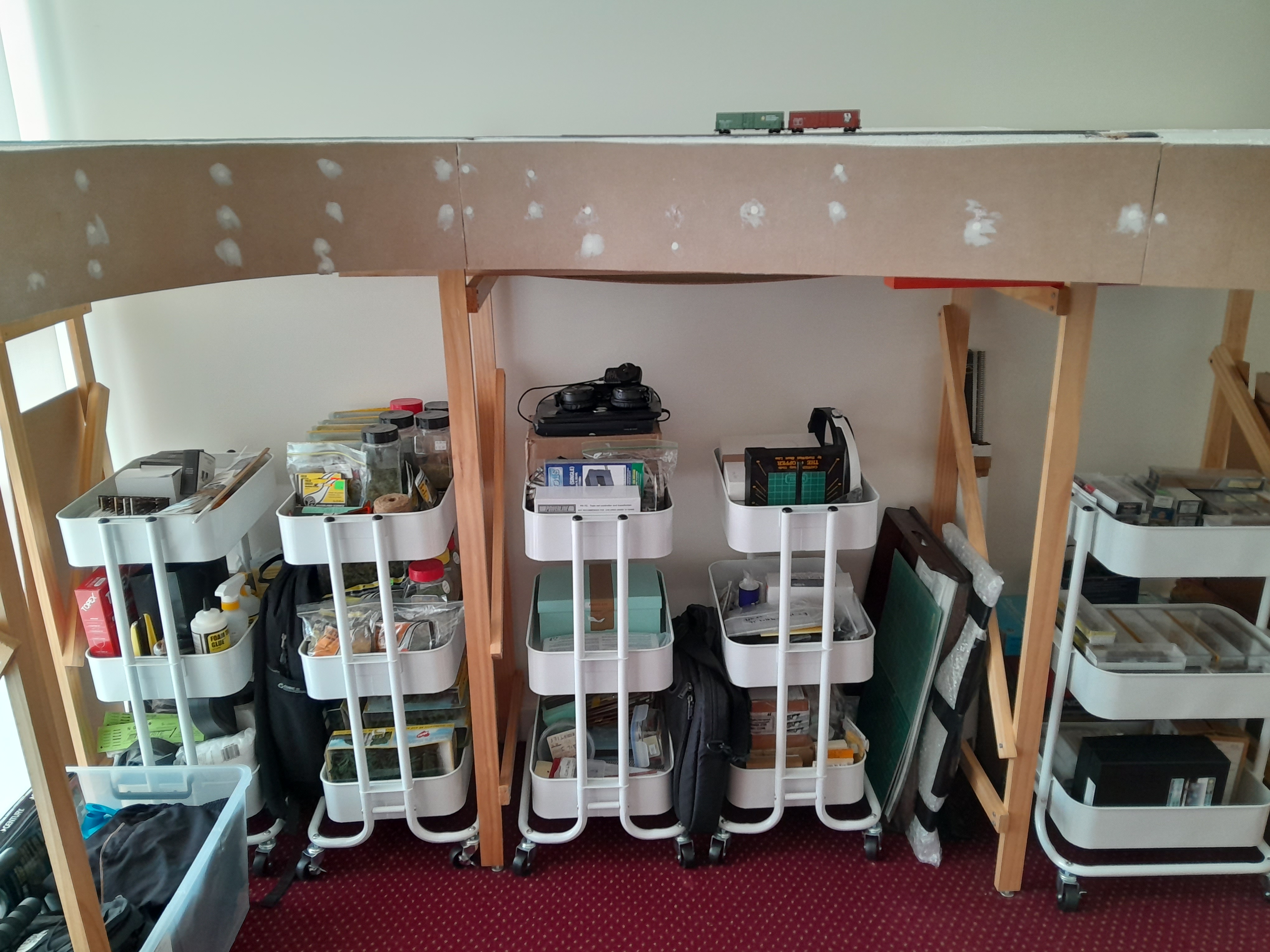
For well over a year, all my rolling stock, kits, paints, decals, tools and hobby supplies have been confined to a series of stacked boxes and tubs in storage making it impossible to find anything quickly. With time off over the Australian summer holidays I finally pulled them all out and put their contents in a series of wheeled carts which fit under the layout.


These particular carts were purchased from the Lincraft chain of stores but I did note that IKEA sells virtually identical ones. I like the fact that I can see the contents easily and wheel the carts around when I need to get access under the layout, or if I want to remove a section from the layout and work on it on my portable workbench. It took a full day to get things fully organized but this will be a huge timesaver moving forward.
Eventually the storage carts will be hidden behind a fascia curtain, but that cosmetic addition will be a few years away yet.

Because of my focus on 1970s PGE and BCR I am happy to report that all my motive power and rolling stock currently fits in one of these carts (the one on the right in the image above). I am sure the collection may grow to two carts over the years, but so far I have been very disciplined in collecting only models appropriate for my period and location.
Fascia Installation
December 23, 2023
The last few weeks have seen the installation of the front fascia on the five layout sections. The fascia is both structural and cosmetic, helping to firmly anchor the foam scenery to the rest of the benchwork while providing a pleasing visual frame to the layout.

The fascia is made from 3mm MDF board which is far easier to cut with a hand saw than traditional tempered hardboard commonly used for model railroad fascia and backdrops. It also bends easier than hardboard which came in handy for the two end modules where single pieces of MDF are curved in excess of 180 degrees.

Because of the flowing organic shape of the layout, I had to add quite a few additional fascia supports to the L Girder benchwork and this was quite awkward and time consuming, but the result is very pleasing with the fascia flowing smoothly even across the four section joins and providing a very strong frame for the foam scenery.


Fascia was mounted with thick construction adhesive and screws and the counter-sunk screw holes were then filled and sanded. I decided that the fascia should be permanently fixed as there is no need for it to be removable when the layout wiring is easily accessible from underneath. I also wanted a smooth finish without any visible screw heads showing.
Once sanded and primed the fascia will likely be painted a shade of light green similar to PGE / BCR light green.


Section 4 and 5 Benchwork
November 12, 2023
Over the last couple of months I have brought Section 4 and 5 to rough completion by adding rough foam insulation board to the L-Girder benchwork. With this the layout foundation is basically complete and is now up on its legs.
Section 4 and 5 represent the north end of Beatton River siding and the curve that leads towards the Beatton River bridge on the prototype.

Section 4 is relatively simple and largely flat so was completed fairly quickly by fixing a large slab of green insulation foam to the L-Girder framework. A few smaller offcuts were used to complete it.


Section 5 was complicated by the fact that Bunnings seemed to be entirely out of the green insulation foam at all Queensland stores. I only needed one sheet of course. Rather than wait I just rounded up all my random offcuts of foam of different types (including some florist foam bricks) and patched together a pretty rough looking surface. Of course, a few weeks after patching this all together, Bunnings had foam back in stock. This time it was blue and much denser. I was used to bad supply chains in New Zealand but it seems to plague Australia too (especially building materials) so the lesson here is to buy everything you need for layout benchwork up front and not on an as-you-need it basis.


Both sections used the standard double layer of N scale on top of HO scale roadbed. They were painted with the surplus off white paint used on the other sections. With this done, the legs were installed and the sections set up in the layout room. The layout sits at 58 inches off the floor which was a deliberate choice to get that realistic near eye level viewpoint. Despite being only 8ft x 9.5ft, the layout looks quite large from this elevated vantage point. I am also pleased with the continually curving flow of the track bed which is a complete contrast to all my prior layout efforts which have been very linear and largely based on hollow core doors.


Next step is to install the front fascia to get a somewhat finished appearance. With this done and some fine tuning of the foam terrain profiles, the new year should see some track getting laid.
Section 3 Benchwork Progress
September 9, 2023
This week has seen the rough completion of Section 3 which is the largest of the five sections of the Beatton River layout. It is one of three free standing sections. Section 3 is 3 feet by 3.5 feet and is supported on three sets of legs.

As with the previous sections, large slabs of green insulation foam were used to form the base terrain and sheets of craft Styrofoam were added to create subtle areas of elevation. The messy process of rasping, sanding and carving the foam was repeated with just as much mess as before. Track bed was built up with N gauge roadbed on top of HO gauge roadbed.
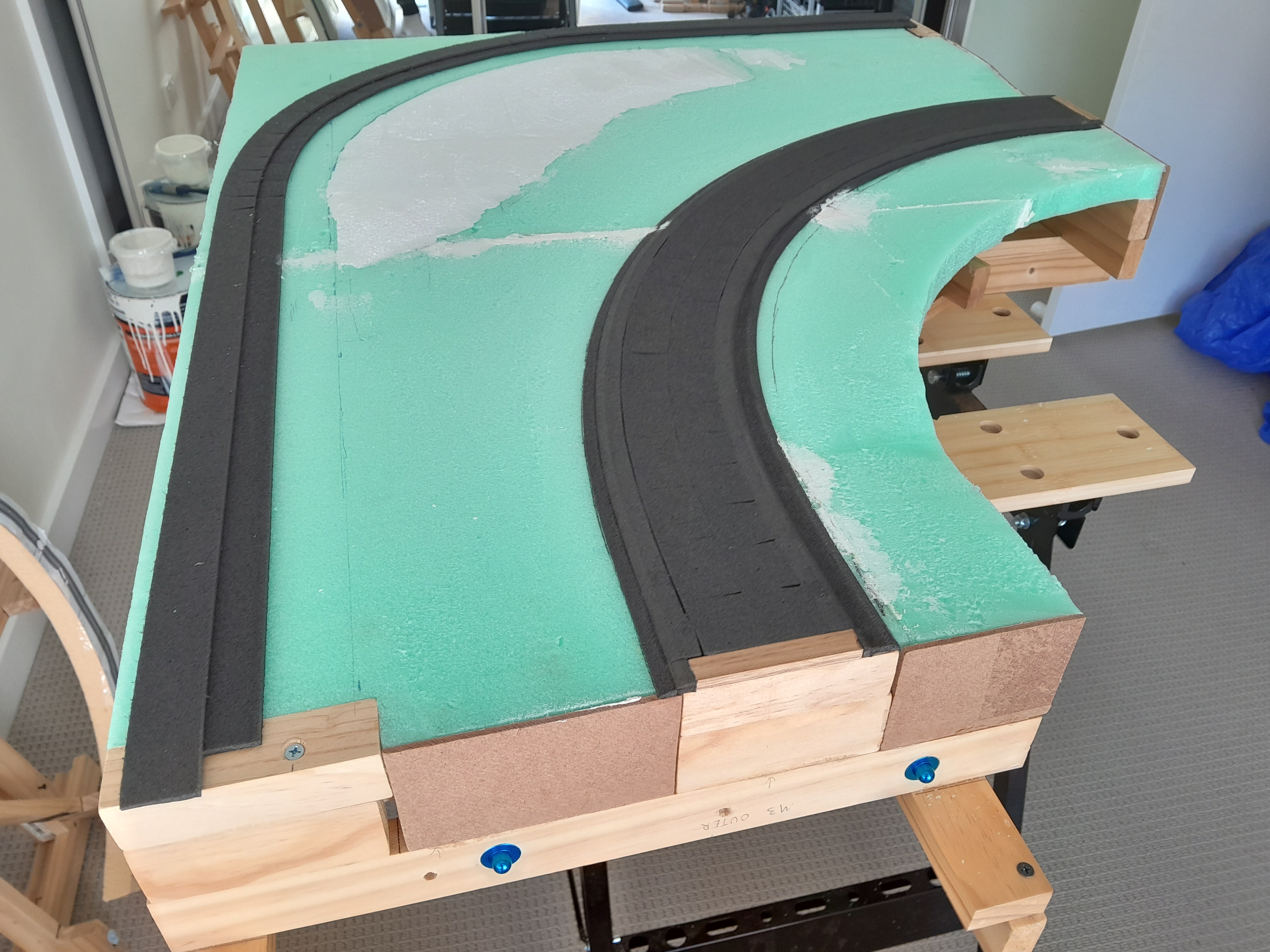
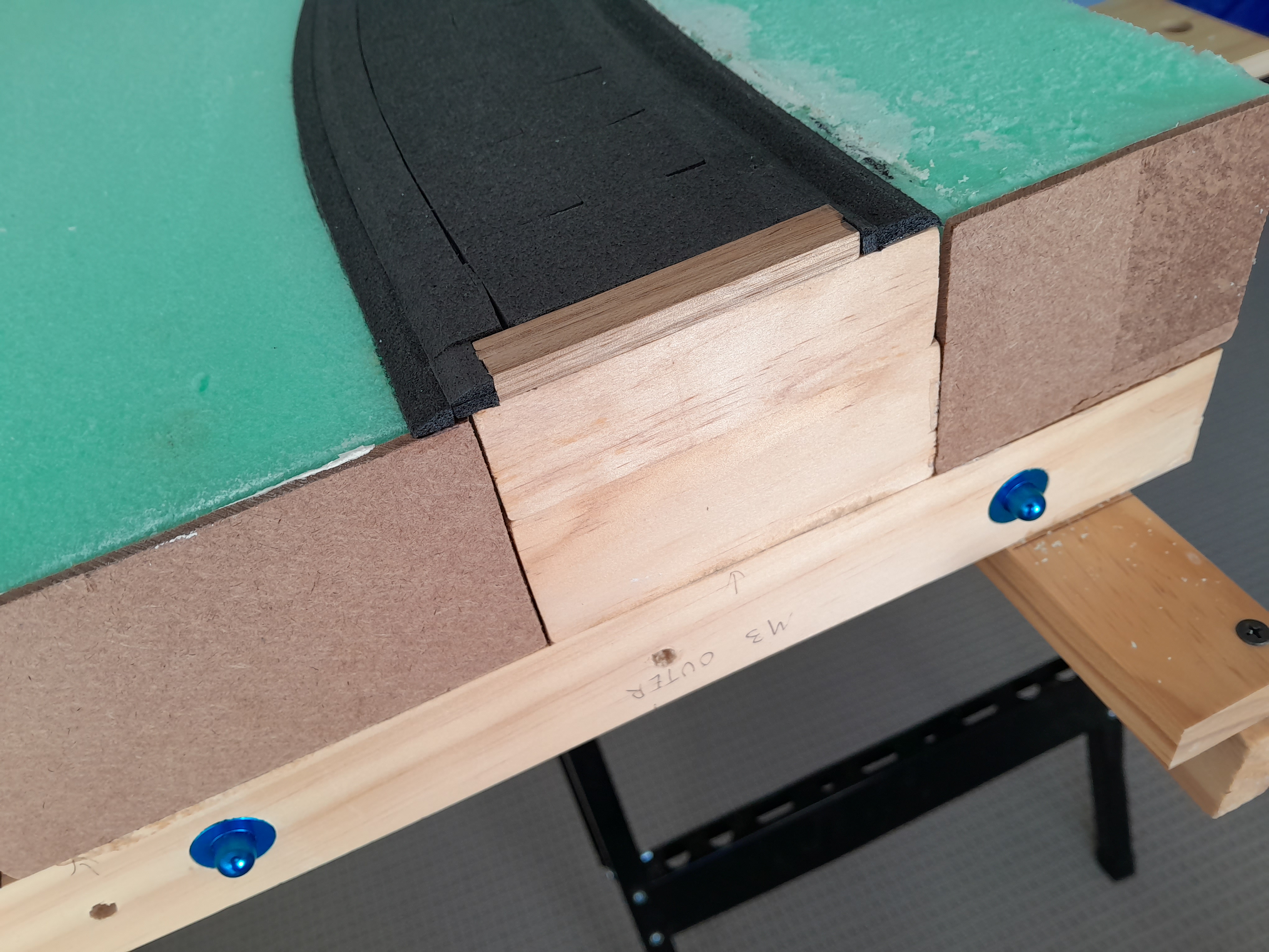


The joins use DCC Concepts precision alignment dowels and carriage bolts. The roadbed transitions from foam roadbed to hard Tasmanian Oak stripwood at the interface points as these will be used to secure PCB ties to which the rail ends will be soldered.
As with the previous sections, several coats of surplus off white paint were used to seal the foam. This has the effect of making it look like I am planning to model winter (something I have in fact considered), but a more suitable earth tone will be used prior to the scenic treatment stage as I am quite set on the idea of early fall 1978 as the season.

With three of five modules at the rough completion stage, they were laid out on the floor, and I am happy to report that they do indeed fit the room!


Two more sections to go. I have noticed that living in a perpetually warm and sunny climate means I spend a lot less time on indoor hobbies as I did when I lived in Canada, which explains the somewhat “relaxed” pace of construction.
Section 2 Progress
July 18, 2023
The somewhat glacial progression of Beatton River continues with the completion of Section 2. This is one of the two smaller bridge sections that is supported by free-standing sections on either side of it.
The same standard steps were used as for Section 1. An insulation board (green foam) base was glued down to the underlying benchwork using latex caulk adhesive. Below grade features were cut into this foam using a combination of knives, saws, rasps, hot wire cutters and sandpaper. Major gaps and holes were filled with lightweight joint compound. Above grade features were added using sheets of white Styrofoam from a local craft store

The roadbed itself uses my time-honoured method of N scale roadbed stacked on top of HO scale roadbed for that prominent raised right of way typical of the BCR north end. The staging yard roadbed has been laid to the width of a single track for now and will be expanded out later (likely to 3 tracks) once the exact track layout of staging has been fine tuned.
Once rough terrain shaping was complete the whole surface was given several coats of off-white paint to seal the foam. I will be fine tuning all the terrain profiles with Sculptamold once all benchwork sections have been completed to this rough format.


Note my treatment of benchwork connection which uses precision alignment dowels, carriage bolts and a hardwood endplate for the roadbed at the join interface (to facilitate firm mounting of track to either PCB ties or brass screws. These will be described in detail in a future post.
In the photo below, staging runs along the right-hand side of the benchwork and will be hidden from view by a thick line of trees.

The large free standing central section (Section 3) is next!.
Section 1 Benchwork Progress
June 16, 2023
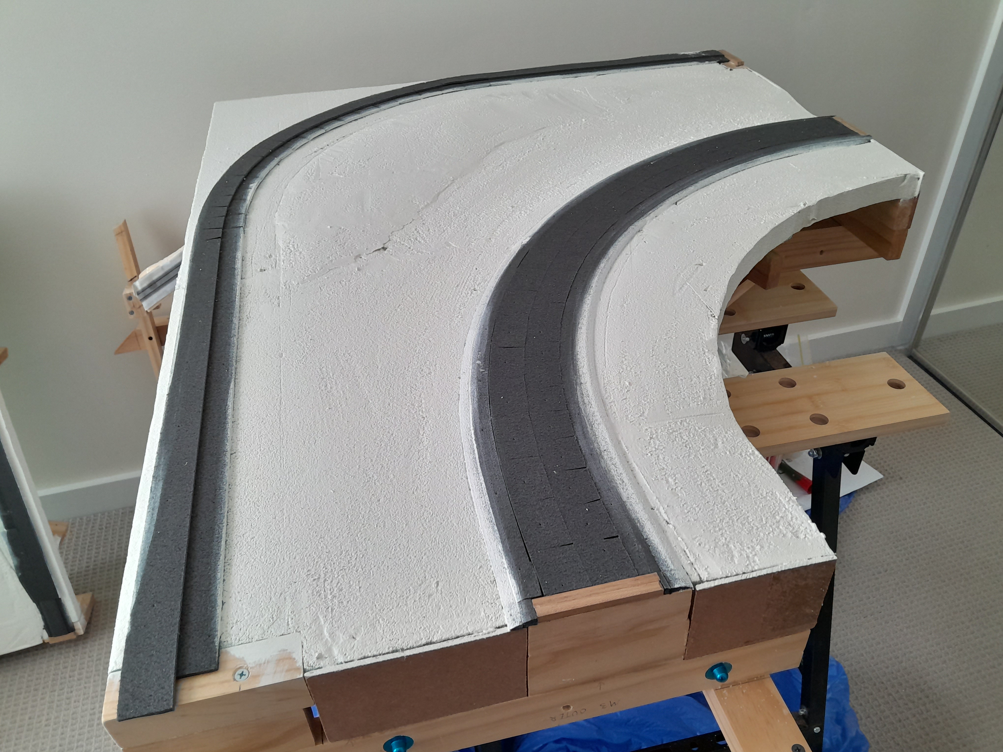
The last few weeks have seen progress on the benchwork. I am working section-by-section getting the basic foam terrain and roadbed down and have finished this rough completion stage for Section 1.
Section 1 represents the south end of the Beatton River scene where the track emerges from the hidden staging and sweeps round a curve towards the south switch at Beatton. Section 1 is one of the smallest and lightest sections of the layout and is also relatively simple as it is just a single-track curve.
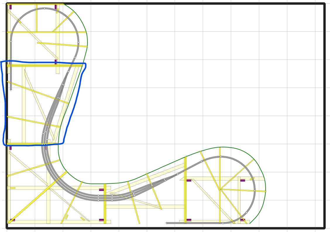
The image below shows Section 1 (highlighted in blue) in the context of the whole layout.

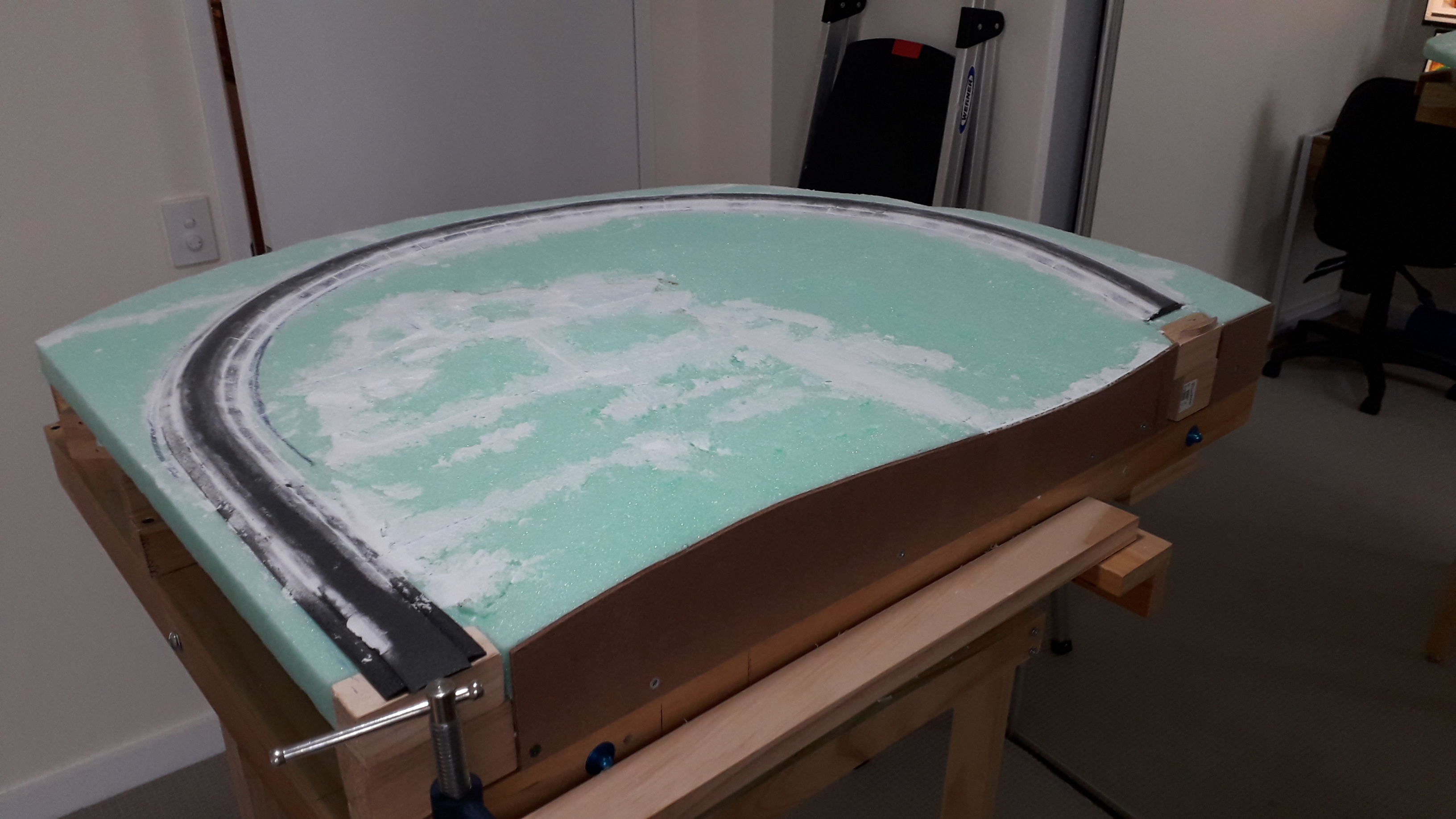
The first step was cutting and installing the foam scenery base using green insulation foam board of the type that is standard in Australia. This cuts very easily with a fine hacksaw, or hot wire cutter (the latter preferable as it results in a lot less mess). The basic shapes were then secured to the L-Girder framework using standard latex adhesive caulk and left to dry thoroughly with plenty of weight placed on top. The standard 2ft x 4ft foam panels were not big enough to cover the surface in one piece, so several pieces were used, and additional risers placed along the joins for support.

The terrain around Beatton River is generally flat and marshy with very gentle undulations. The foam was carved down below track grade in some areas and built up slightly in others using thin offcuts of additional foam glued down with PVA.
The roadbed is often the highest point of terrain in this part of the world and, due to the marshy conditions, was built up on quite a substantial fill along most of the line (the Fort Nelson subdivision was notorious for continually sinking into marshy wetland) To reproduce the broad elevated roadbed, I used a base of HO scale track bed with N scale trackbed on top of it. I used the Australian Trackrite brand of foam roadbed for this purpose and the effect is quite convincing even at this non-scenic stage.
The very messy (but strangely satisfying) part of the whole process was going over the rough terrain with carving knives, hacksaws, hot wire foam cutters and a rasp to get the final relatively smooth terrain contours. The various gaps and holes caused by the rasping were patched up with lightweight joint compound and some rough blending of the roadbed-terrain interface was also done.


The advantage of the layout sections being small and light is that they can just be clamped to a portable workbench for easy access on all sides.
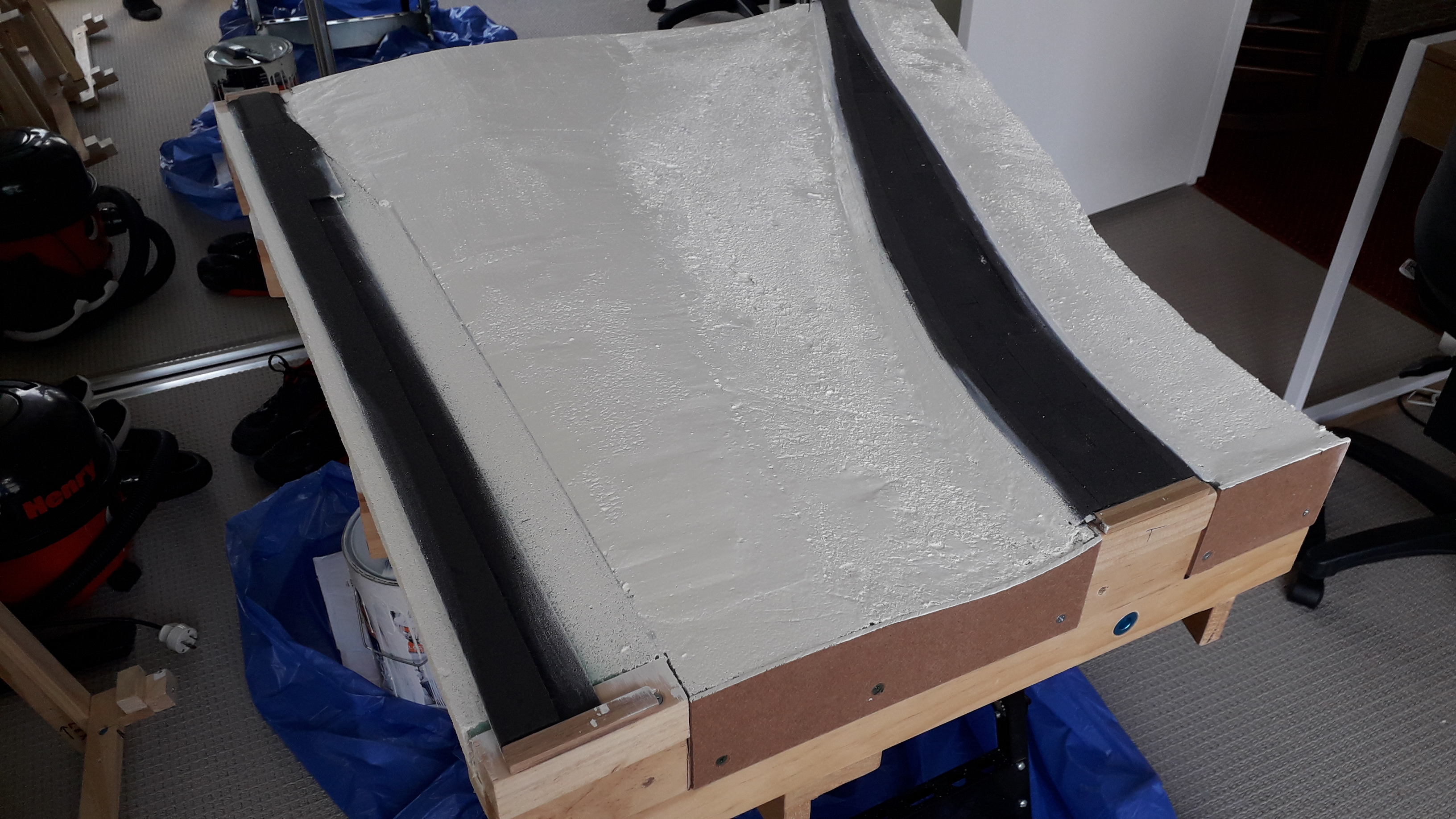
The final step was to give the whole terrain base several coats of paint to seal it. 3 or 4 coats of surplus off-white paint were used. This is not the final terrain colour, but the foam does need to be sealed as it does tend to flake and generate dust (unlike the North American pink or blue foam which is much denser). The terrain contours around the roadbed will be improved with Sculptamold at a later stage and then painted with a suitable earth colour.
The front fascia is noticeable by its absence, but the plan is do all the messy, noisy cutting of fascia boards in one session, once this foam terrain step has been completed on all the remaining sections.

Next post will document this process on Section 2.
